- Home
- About
- Training Courses
- ASME Courses
- API Courses
- API 510 Pressure Vessel
- API 570 Process Pipework
- API 653 Aboveground Storage Tank
- API 936 Refractory Personnel
- API 580 RBI Online
- API 580 RBI Classroom *New*
- API 571 Corrosion & Materials Online
- API 571 Corrosion & Materials Classroom *New*
- API 577 Welding Inspection & Metallurgy Online
- API 510 CPD Training
- API 570 CPD Training
- API 1169 Pipeline Construction
- API SIFE Source Inspector Fixed Equipment
- API SIRE Source Inspector Rotating Equipment
- E-Learning
- Technical Courses
- API CPD Recertification
- Training Courses
- Technical Hub
- Virtual Training
- FAQs
- Contact
- Online Training Portal
- Shop

- In: Training | On: Jul 6, 2021
Back to basics – Material Properties
This article ‘Back to basics – Material Properties’ covers the essential properties when considering asset integrity. Material science in itself is a huge subject, with endless reference books and academic courses that cover the subject. Only a high-level understanding will be provided in this article.
Stakeholders should be concerned with ensuring pressure equipment is safe to operate and the pressure boundary does not degrade to such an extent that it poses a risk of failure. Think of it like this – when a pressure vessel is inspected, it is the material of construction that is inspected. The material happens to have been used to construct a pressure vessel, but it’s the base material and the welds that are examined to ensure they continue to have the capacity to sustain the demand.
The demand on a material can be exerted in the form of:
• Pressure (internal and/or external)
• Weight
• Vibrations
• Mechanical and/or Thermal Cycles
• Temperature
• Flow velocities
It is the material properties that influence the capacity to sustain these loadings. Therefore, it is important that
those responsible for the inspection and assessment of pressure equipment have at least, a basic understanding
of the key mechanical properties that affect pressure equipment performance.
The key mechanical properties discussed in this chapter are:
1. Yield Strength
2. Ultimate Tensile Strength
3. Toughness
4. Ductility
5. Hardness
These will be covered in more detail later.
The most commonly used material in the fabrication of pressure equipment is steel. It comes in many forms
and types, but it is mainly carbon and stainless steel that is utilised, and these will therefore be the ones covered
in this course.
Materials used for pressure equipment can be classified into two categories, metallic and non-metallic. Metallic
materials can be further divided into; ferrous and non-ferrous materials.
Carbon Steels
Carbon steels are considered as those containing less than 1% carbon. Carbon steels are classified into three groups, based on their carbon content;
• Low (<0.25%)
• Medium (0.25 to 0.6%)
• High (0.6%-1%)
• Very High (1%-1.5%)
Low
Often called mild steels, low-carbon steels have less than 0.30% carbon and are the most commonly used grades. They machine and weld nicely and are more ductile than higher-carbon steels.
Medium
Medium-carbon steels have from 0.30 to 0.60 % carbon. Increased carbon means increased hardness and tensile strength, decreased ductility, and more difficult machining.
High
With 0.60 to 1% carbon, these steels can be challenging to weld. Preheating, post-heating (to control cooling rate), and sometimes even heating during welding become necessary to produce acceptable welds and to control the mechanical properties of the steel after welding.
Very High
With up to 1.50 % carbon content, very high-carbon steels are used for hard steel products such as metal cutting
tools and truck springs. Like high-carbon steels, they require heat treating before, during, and after welding.
Alloy Steels
These steels contain specified amounts of alloying elements such as, chromium (Cr), nickel (Ni), molybdenum
(Mo), manganese (Mn), vanadium (V), silicon (Si), aluminium (AL) and copper (Cu).
Low-alloy Steels
When these steels are designed for welded applications, their carbon content is usually below 0.25 % and often below 0.15%. Typical alloys include nickel, chromium, molybdenum, manganese, and silicon, which add strength at room temperatures and increase low-temperature notch toughness.
In the right combination, these alloys can improve corrosion resistance and influence the steel’s response to heat
treatment. But the alloys added can also negatively influence crack susceptibility, hence the use of low-hydrogen
welding processes with them. Preheating might also prove necessary. This can be determined by using the carbon
equivalent formula which will be covered later.
High-alloy Steels (Stainless Steels)
For the most part, we’re talking about stainless steel, the most important commercial high-alloy steel. Stainless
steels contain at least 11% chromium, and many have high nickel contents. The three basic types of stainless are:
1. Austenitic
2. Ferritic
3. Martensitic
Martensitic stainless steels make up the cutlery grades. They have the least amount of chromium, offer high
hardenability and require both preheat and post-heating when welding to prevent cracking in the heat-affected
zone (HAZ).
Ferritic stainless steels have 12 to 27% chromium with small amounts of austenite forming alloys.
Austenitic stainless steels offer excellent weldability, but austenite isn’t stable at room temperature. Consequently,
specific alloys must be added to stabilise austenite. The most important austenite stabiliser is nickel, and others
include carbon, manganese, and nitrogen.
Special properties, including corrosion resistance, oxidation resistance, and strength at high temperatures, can be
incorporated into austenitic stainless steels by adding certain alloys like chromium, nickel, molybdenum, nitrogen,
titanium, and niobium.
While carbon can add strength at high temperatures, it can also reduce corrosion resistance by forming a compound
with chromium. It’s important to note that austenitic alloys can’t be hardened by heat treatment. That means they
don’t harden in the welding HAZ.
Material Properties
It’s important that those responsible for inspecting and assessing static mechanical pressure equipment have a reasonable understanding of the various mechanical properties of steel. The following section will provide a basic understanding of the key properties required for pressure equipment.
Strength
Tensile testing is used to determine a metal ultimate tensile strength, yield strength, elongation and reduction in
cross-sectional area. The test is performed by pulling a test specimen in tension with increasing load until a fracture
occurs. During the test, an engineering stress/strain curve is produced by plotting the elongation of the specimen
as a result of the load applied.
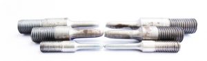
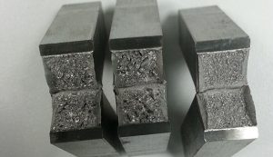
Back to basics – Material Properties – Tensile test specimens
Yield stress
Yield stress is the amount of stress required to permanently deform a material. Stress is calculated by dividing
the force that is being exerted on an object by its cross-sectional area. Thicker materials are able to withstand
higher forces so by using stress instead of just force, we are able to use the same yield stress for the same material,
regardless of how thick it actually is. To compute the amount of stress acting on the object, use the equation:
Stress = Force/Area
Another important concept is strain, how much an object deforms when forces are applied to it. Most of the time
this deformation will either cause the object to elongate or shorten, depending on how the forces are applied. To
compute strain, the change in length is divided by the object’s original length.
Strain = Change in length/Original length
Longer specimens will have a greater change in length than smaller specimens, even though they experience the
same forces acting on them. The amount of this extension and the reduction of the cross-section area is a measurement
of the ductility of the material.
Elastic deformation will automatically reverse itself when external forces are removed. Imagine a rubber band – no matter how you stretch it, once you let go of one end it will ‘snap’ back to its original
shape.
Elasticity
Is the ability of a deformed material body to return to its original shape and size when the forces causing the
deformation are removed. A body with this ability is said to behave (or respond) elastically.
To a greater or lesser extent, most solid materials exhibit elastic behaviour, but there is a limit to the magnitude of
the force and the accompanying deformation within which elastic recovery is possible for any given material.
This limit is called the elastic limit, or more commonly known as the yield point, and is the maximum stress or
force per unit area within a solid material that can occur before the onset of permanent deformation. Stresses beyond the elastic limit cause material to yield or flow.
For such materials, the elastic limit marks the end of elastic behaviour and the beginning of plastic behaviour.
In a simple tension test, the strain is proportional to the stress, indicated by the straight line on the stress/strain
plot. Removal of the load prior to the yield point will cause the specimen to return to its original length and shape.
Back to basics – Material Properties – Stress Strain Curve
Plasticity
Once the material has yielded, or in other words, when the material has permanently deformed, it is undergoing
non-reversible changes of shape in response to applied forces. It is now under plastic deformation. For most steels,
the load required to continue elongation must continue to be increased as seen in the plastic range section of the
stress/strain plot. The material is getting stronger due to work hardening.
Work hardening (strain hardening) is a consequence of plastic deformation and is the strengthening of a metal
by plastic deformation. This strengthening occurs because of dislocation movements and dislocation generation
within the crystal structure of the material. This phenomenon will continue to the point known as the Ultimate
Tensile Stress.
Ultimate Tensile Stress (UTS)
The UTS is the point at which necking becomes substantial, it causes a reversal of the engineering stress-strain
curve because the engineering stress is calculated assuming the original cross-sectional area before necking. The
reversal point is the maximum stress on the engineering stress-strain curve, and the engineering stress coordinate
of this point is the ultimate tensile strength, given by point C.
The necking will continue to occur until complete rupture of the specimen if the load continues to be applied. Once
ruptured, the specimen is measured to obtain the change in length and to establish the reduction in cross-sectional
area. This is used to determine the ductility of the material.
Allowable (Design) Stress
The allowable stress or allowable strength is the maximum stress (tensile, compressive or bending) that is permitted
to be applied to a material. The allowable stresses are generally defined by codes. For steel and aluminium, it is
a fraction of their yield stress or UTS. This allows a safety margin when designing components.
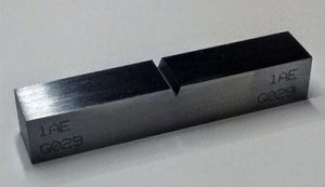
Ductility
This is best defined as the ability of a material to deform plastically without fracturing and is measured by the
elongation (a) and/or the reduction of cross-sectional area (b) of the specimen. The specimens can be punch-marked and measured prior to, and after testing.
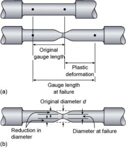
Back to basics – Material Properties – Tensile test
The change in length is divided by the original length to provide a ductility value as a percentage. Ductile materials
can typically be plastically elongated by more than 15% before they fracture.
Toughness
Fracture toughness is an important property in the design of pressure equipment as it determines the ability of the material to hold a crack stable under load and not to let the crack rip open. Impact toughness is the ability of a material to absorb impact (energy) and plastically deform without fracturing and is commonly determined by the Charpy impact test.
Toughness is a function of temperature and thickness. As the temperature of the material decreases, so does the toughness. As the thickness of a material increases the toughness decreases. Materials are often tested at various temperatures
to determine the ductile to brittle transition temperature, also known as the ‘Fracture Appearance Transition Temperature (FATT).
Many codes require impact testing to be carried out at the minimum design temperature to ensure the material exhibits sufficient toughness to resist brittle fracture.
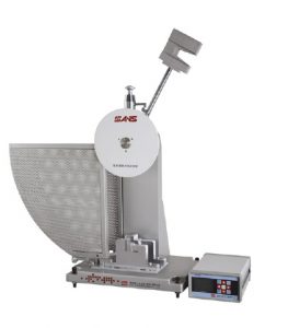
Charpy Impact Testing
The test used is a destructive method utilising three specimens machined from actual production test plates or sample materials. The test samples can be machined for impact testing all base materials, weld metals or the heat-affected zone (HAZ). Standard test specimens are 10mm x 10mm x 55mm long with a 2mm deep 45º notch (groove) cut into the specimen.
The many codes allow for sub-size specimens to be used for tests.
Note: The specimens are usually cooled in liquid nitrogen and allowed to warm to the exact temperature required for testing.
Hardness
Hardness is the resistance to plastic deformation by indentation, which is measured by various test methods including;
Brinell, Rockwell, Knoop and Vickers.
Reasons for hardness testing;
1. NDE method to determine the hardness of the finished product
2. Can be used as an approximate correlation of the UTS of materials
3. Verifies that the material exhibits the desired mechanical properties following heat treatment
Nearly all of our training courses cover the basic mechanical properties of metals. It is such a vital subject to know when dealing with the mechanical integrity of pressure equipment, yet sadly it’s common for the topic to be our delegates weakest link in their knowledge.
To find out more about our Materials and Corrosion courses, take a look at our learning API 571 course. This in-depth and technically challenging course covers all the damage mechanisms in API 571.
