- Home
- About
- Training Courses
- ASME Courses
- API Courses
- API 510 Pressure Vessel
- API 570 Process Pipework
- API 653 Aboveground Storage Tank
- API 936 Refractory Personnel
- API 580 RBI Online
- API 580 RBI Classroom *New*
- API 571 Corrosion & Materials Online
- API 571 Corrosion & Materials Classroom *New*
- API 577 Welding Inspection & Metallurgy Online
- API 510 CPD Training
- API 570 CPD Training
- API 1169 Pipeline Construction
- API SIFE Source Inspector Fixed Equipment
- API SIRE Source Inspector Rotating Equipment
- E-Learning
- Technical Courses
- API CPD Recertification
- Training Courses
- Technical Hub
- Virtual Training
- FAQs
- Contact
- Online Training Portal
- Shop

- In: Training | On: Jul 5, 2021
Pressure Relief Valves
Pressure Relief Valves – Pressure equipment requires protection from over pressurisation. A common way to protect vessels is the installation of a pressure relief valve. A pressure relief device is actuated by inlet static pressure and designed to open during an emergency or abnormal conditions to prevent a rise of internal fluid pressure above the specified design value. This device may also be designed to avoid an internal vacuum.
The sizing of valves is very important. To find out what happens if this is not done correctly, have a look at this article. Equally important to the design of the valve, is the in-service inspection and maintenance. The Health and safety Pressure System guide also highlights the need to have safety valves in place.
The term PRD should be thought of as an encompassing term to cover all types of devices. Thus, the main types of pressure relief devices can be considered as falling into three distinct categories.
- Reclosing type (Pressure Relief Valve)
- Vacuum type
- Non-reclosing type
Common examples of these types include; direct spring-loaded pressure relief valves, pilot-operated pressure-relief valves, rupture disks, weight-loaded devices and pressure and/or vacuum vent valves.
A pressure relief valve (PRV) is designed to open for the relief of excess pressure and reclose, thereby preventing further flow after normal conditions have been restored. A PRV may be used for either compressible or incompressible fluids, depending on the design, adjustment or application.
Therefore, PRV is a general term, including safety valves, relief valves, conventional safety relief valves, balanced safety relief valves, and pilot-operated relief valves. The names ‘safety’ and ‘relief’ are frequently used interchangeably, but they should not be.
Safety valves are for compressible fluids, steam and other gases. This compressibility demands quick overpressure relief. So, safety valves have pop seats and plugs which open rapidly on overpressure, relieving at full flow. They may discharge steam into the atmosphere or direct a gas back to the system.
Relief valves are for non-compressible fluids-liquids such as water and oil. Immediate full-flow discharge is unnecessary since a minimal flow significantly reduces overpressure, so the plug and seat open and close very slowly, discharging back to some low-pressure point in the system to conserve the liquid.
Pressure relief devices protect pressurised systems from exceeding the design pressure, but where does this excess pressure come from. Examples include but are not limited to;
• An imbalance of fluid flow rates caused by the closing and opening of isolation valves
• Failure of a cooling system, allowing vapour or fluid to expand
• Compressed air or electrical power failure to control instrumentation
• Transient pressure surges
• Heat exchanger tube failure
• Uncontrollable exothermic reactions in chemical plants
• Ambient temperature changes
Definitions
A relief valve is a spring-loaded pressure relief valve actuated by the static pressure upstream of the valve. The valve opens typically in proportion to the pressure increase over the opening pressure. A relief valve is used primarily with non-compressible fluids.
A safety valve is a spring-loaded pressure relief valve actuated by the static pressure upstream of the valve and characterised by rapid opening or pop action. A safety valve is generally used with compressible fluids.
A safety relief valve is a spring-loaded pressure relief valve that may be used as either a safety or relief valve, depending on the application.
PSV Classification
There are generally two types of PSV.
- Direct Acting PSV
- Pilot Operated PSV
Direct Acting
The oldest and the most commonly used type of PSV is the direct-acting type. They are designed as direct-acting because the force element that keeps the valve closed is either a weight, a spring or a combination of both. The process to be relieved acts directly on a disc that is held closed by the spring force opposing the lifting process pressure.
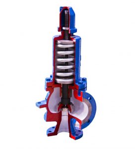
Spring-Loaded Design
The image below shows the construction of a conventional spring-loaded PSV. The valve consists of a valve inlet or nozzle mounted on the pressurised system, a disc held against the nozzle to prevent flow under typical system operating conditions, a spring to hold the disc closed, and a body and bonnet to contain the operating elements.
The spring load is adjustable to vary the pressure at which the valve will open; when PSV begins to lift, the spring force increases. Thus, system pressure must increase if the lift is to continue. For this reason, pressure relief valves are allowed an overpressure allowance to reach full lift. This allowable overpressure is generally 10% for valves on unfired systems.
This margin is relatively small, and some means must be provided to assist in the lift effort. Most pressure relief valves, therefore, have a secondary control chamber or huddling chamber to enhance lift. As the disc begins to lift, fluid enters the control chamber, exposing a larger surface area for the pressure to act against.
This causes an incremental change in force that overcompensates for the increase in spring force and causes the valve to open rapidly. At the same time, the direction of the fluid flow is reversed, and the momentum effect resulting from the change in flow direction further enhances lift.
These effects combine to allow the valve to achieve maximum lift and maximum flow within the allowable overpressure limits. However, because the larger disc area is exposed to system pressure after the valve achieves lift, the valve will not close until system pressure has been reduced to some level below the set pressure. The design of the control chamber determines where the closing point will occur.
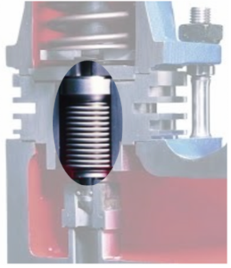
Huddling Chamber
What is a huddling chamber? An annular chamber located downstream of the seat of a pressure-relief valve to assist the valve in achieving lift.
Force is equal to Pressure x Area. Therefore, the huddling chamber allows an increase in force by increasing the area by which the force can be exposed and applied, enhancing the lift.
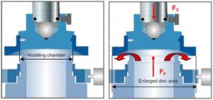
From the diagram above, it can also be seen that the shroud reverses the direction of flow, further enhancing lift. This causes a rapid opening and the popping action as these forces overcompensate for the increase in spring force
Accumulation
The pressure increase over the maximum allowable working pressure (MAWP) of the vessel or piping system, expressed in pressure units or as a percentage of MAWP or design pressure if a MAWP has not been established. Maximum allowable accumulations are established by applicable codes for an emergency, operating, and fire contingencies. See pages 13 & 14 for illustrated examples of these.
Set Pressure
The pressure increase, over the set pressure of the relieving device. Overpressure is expressed in pressure units or as a percentage of set pressure. Overpressure is the same as accumulation only when the relieving device is set to open at the MAWP of the vessel.
Over Pressure
The value that the valve is set at to start relieving pressure. This is set to below MAWP and can be set at MAWP.
Maximum Allowable Working Pressure (MAWP)
The maximum gauge pressure permissible at the top of a vessel in its operating position at the designated coincident temperature specified for that pressure.
The pressure is the least of the values for the internal or external pressure as determined by the vessel design rules for each element of the vessel using the minimum or average thicknesses for all critical vessel elements (exclusive of additional metal thickness allowed for corrosion and loadings other than pressure) and adjusted for applicable static head pressure
It may also be adjusted during the life of the equipment as corrosion consumes the wall thickness beyond the original design CA. This may be done as part of a re-rating.
The MAWP is the basis for the pressure setting of the pressure-relief devices that protect the vessel. The MAWP is normally greater than the design pressure but can be equal to the design pressure when the design rules are used only to calculate the minimum thickness for each component of the vessel, and is adjusted for the static head.
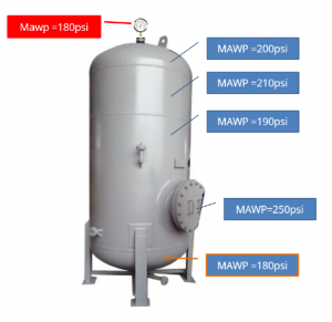
It is the limiting component that dictates the MAWP, and in this case, the MAWP is 180psi.
Static Head Pressure
The static head is the pressure exerted by the weight of a fluid. The higher the fill height of a vessel or tank, the greater the weight of the fluid and, therefore, the greater the pressure exerted on the walls and bottom of the component.
The pressure exerted can be calculated by multiplying the fill height (per foot) by 0.433 psi (this assumes water, which being dense is generally used regardless of the intended fluid service).
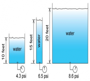
A vessel with a total height of 100 feet with no other internal pressure other than static head pressure would show 43.3 psi on a pressure gauge fitted at the very bottom when full of water. The gauge at the very top would read 0 psi as there is no water acting on it.
It is important to note, therefore, that MAWP is always adjusted for the static head.
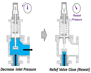
Reseating
Once normal operating conditions have been restored, the valve is required to close again, but since the larger area of the disc is still exposed to the fluid, the valve will not close until the pressure has dropped below the original set pressure.
The blowdown is usually less than 10% for compressible fluids, and for liquids, it can be up to 20%. The difference between the set pressure and the closing point pressure is called blowdown and is usually expressed as a percentage of set pressure.
Back Pressure
Pressure relief valves on clean, non-toxic, non-corrosive systems may be vented directly to the atmosphere. Pressure relief valves on corrosive, toxic or valuable, recoverable fluids are vented into closed systems.
For valves installed in a closed system or when a long vent pipe is used, there is a possibility of developing high backpressure. Therefore, the back pressure on a PRV must always be evaluated, and its effect on valve performance and relieving capacity must be considered.
Conventional Valves
Superimposed backpressure may result from the valve outlet being connected to a normally pressurised system or caused by other pressure relief valves venting into a common header. Compensation for superimposed backpressure, which is constant, may be provided by reducing the spring force.
Under this condition, the force of the spring plus backpressure acting on the disc would equal the force of the inlet set pressure acting to open the disc. However, it must be remembered that the set pressure value will vary directly with any change in backpressure.
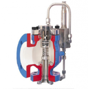
Balanced Bellow Valve
When superimposed back pressure is variable, a balanced bellow or balanced piston design is recommended. A typical balanced bellow is shown on the right. The bellows or piston is designed with an effective pressure area equal to the seating area of the disc.
The bonnet is vented to ensure that the pressure area of the bellows or piston will always be exposed to atmospheric pressure and to provide a tell-tale sign should the bellows or piston begin to leak. Variations in back pressure, therefore, will have no effect on set pressure.
Pilot Operated PSV
A pilot-operated pressure relief valve is a pressure relief valve in which the major relieving device is combined with and is controlled by a self-actuated auxiliary pressure relief valve.
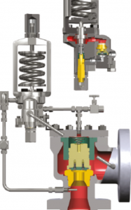
Pilot-operated pressure-relief valves are generally used:
• where a large relief area and/or high set pressures are required;
• Where a low differential exists (operating margin) between the normal pressure equipment (vessel and piping) operating
pressure and the set pressure of the valve;
• On large low-pressure storage tanks;
• Where very short blowdown is required;
• Where backpressure is very high and balanced design is required;
• Where process conditions require sensing of pressure at one location and relief of fluid at another location;
• where inlet or outlet piping frictional pressure, losses are high; and
• where in situ, in service, set pressure verification is desired.
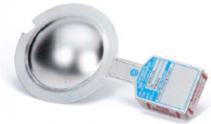
Rupture Discs
Rupture discs are safety devices with a defined breaking point, which respond to a specific pressure and are used for pressure relief in the most diverse applications. They are used to protect against overpressure or vacuum within a process.
The most significant advantage over electronic, pneumatic, or spring-loaded safety systems is the fail-safe performance of rupture discs.
High reliability is essential to prevent unnecessary downtime of the system. However, how fail-safe a rupture disc significantly depends on the craft and the material used.
Different applications require different types of rupture discs. For example, they are made of metals or plastics from one or more layers, and they can be domed or flat.
Domed rupture discs either have the dome towards the process (reverse-acting rupture disc) or away from the process (forward-acting rupture discs). Within these different varieties, there is a broad range of possible combinations.
Rupture discs are either installed directly between flanges or inserted into a corresponding rupture disc holder, then mounted between flanges. Although they are often used to protect the inlet of a PRV from corrosive service conditions, they should be non-fragmenting to prevent damage to the valve when used in this service.
Our PRV Training Course
The ‘Inspection and Maintenance of Pressure Relief Devices’ is a practical training course tailored to the specific needs of companies working with PRDs. It combines classroom instruction and practical workshop training on various types of PRDs.
Who is this course for?
The course is suited to those involved in the inspection, recertification, management of PRV changeout, RBI team
members and staff who may be unfamiliar with PRVs such as graduates or trainees. The training provides the
necessary technical learning in relation to the in-service cycle of a PRV such as;
• Preinstallation inspection and certification compliance
• Installation inspection and monitoring
• In-service inspection
• Removal inspection and pop testing
• Inspection and reporting
• Re-assembly and testing procedures
After completion of the online training, delegates will be able to;
1. Explain the purpose of pressure relief devices.
2. Identify the various types of devices and explain the differences between them.
3. Describe the components and their function.
4. Identify the common damage mechanisms affecting PRDs and their associated function.
5. Explain the in-service inspection and inspection methods, such as Trevitesting.
6. Explain what the inspector’s roles and responsibilities are during the life of a PRD
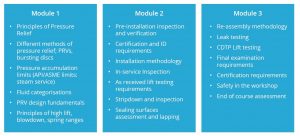
The training provides the necessary technical learning about the in-service cycle of a PRV such as;
- Pre-Installation: The course introduces the checks and Inspection required to receive a PRV before its installation into service. The physical examination is shown along with the correct QA/QC validation on PRV certification.
- Installation: Correct installation of a PRD is crucial to its intended operation. The course will explain the installation process and what to look for, such as misalignment, flange sealing face damage, correct use of gaskets and torquing of the joint.
- In-Service Inspection: Although visual Inspection is often limited while in-service, there are certain aspects covered in the course, such as an introduction to in-service tests such as the ‘Trevitest’ and visual Inspection, ensuring there is no significant damage.
- Stripdown and Inspection: Participants will be involved in the ‘as received’ lift test, strip down, inspection, assessment and reporting on the condition of the valve. We can supply sample used valves for use during the course if required.
- Reassemble and Testing: During this phase of the course, the delegates will have the opportunity to conduct seat lapping and surface finish assessment. In addition, instruction will be given on the reassembly of the valve and the testing.
- RBI & Damage Mechanisms: An introduction to Risk-Based Inspection for PRVs is provided based on current industry practice. Several common damage mechanisms will also be introduced, along with their damage and failure modes.
You can find out more here, or contact us at [email protected].
