- Home
- About
- Training Courses
- ASME Courses
- API Courses
- API 510 Pressure Vessel
- API 570 Process Pipework
- API 653 Aboveground Storage Tank
- API 936 Refractory Personnel
- API 580 RBI Online
- API 580 RBI Classroom *New*
- API 571 Corrosion & Materials Online
- API 571 Corrosion & Materials Classroom *New*
- API 577 Welding Inspection & Metallurgy Online
- API 510 CPD Training
- API 570 CPD Training
- API 1169 Pipeline Construction
- API SIFE Source Inspector Fixed Equipment
- API SIRE Source Inspector Rotating Equipment
- E-Learning
- Technical Courses
- API CPD Recertification
- Training Courses
- Technical Hub
- Virtual Training
- FAQs
- Contact
- Online Training Portal
- Shop

- In: Training | On: Jul 2, 2021
Branch Connections: ASME B31.3 Para. 304.3.2
Calculating Branch Connections: ASME B31.3 Para. 304.3.2 – Whenever a branch is added to the main pipe run (header) an opening is created by the removal of a predetermined amount of metal. We use Branch Connections: ASME B31.3 Para. 304.3.2 to consider the design. The header pipe is weakened as the metal removed is no longer there to resist the forces due to internal and/or external pressure. The area removed must be compensated for by sufficiently restoring the loss of metal by either using:
• a listed type branch connection; or
• by using the ‘area replacement concept’.
Branch connections are considered to have adequate strength to resist the applied loads from internal pressure if it is made to a listed component from either of the following standards; ASME B16.9, ASME B16.11 tee or MSS SP-97 branch connection fitting. There are, however, a few other expectations that must always be met to ensure full compliance with ASME B31.3 Para 304.3.2. This means that no additional reinforcement calculations are required.
• the branch connection is made by welding a listed threaded or socket welding coupling directly to the header in accordance with the welding requirements detailed in para328.5.4, provided the branch is limited to a maximum size of NPS 2 nor one-fourth of the nominal size of the header;
• the minimum thickness of the coupling (anywhere) cannot be less than header;
• Only coupling of class 3000 and over can be used in accordance with ASME B16.11; and•Unlisted branch connections may be used if the material is listed in table A-1 and the branch connection is qualified by methods such as; service experience, experimental stress analysis, proof test or finite element analysis (FEA).
The area replacement concept is used to replace the metal removed by using excess material from the header, the branch, the fillet cover attachment welds or a reinforcement pad when fitted. The code provides a method to limit where the material can be taken from, in both the parallel and perpendicular axis to the header pipe. There are rules with respect to the geometries of the header and branch connection that must be met (304.3.1) when applying the minimum design requirements for a branch connection. These are;
• the header pipe diameter-to-thickness ratio (𝐷ℎ/𝑇ℎ) is < 100 and the branch-to-run diameter ratio (𝐷𝑏/𝐷ℎ) is not greater than 1;
• for header pipe with (𝐷ℎ/𝑇ℎ) ≥ 100, the (𝐷𝑏/𝐷ℎ) must be less than 0.5;
• the angle between the branch and header axes (ß)must be at least 45˚; and
• the axis of the branch must intersect the axis of the header.
Where the above rules are not satisfied the designer may use one of the alternative methods to qualify the connection detailed under the unlisted branch connections (304.7.2). Other design options should also be considered, such as; integral reinforcement or complete encirclement reinforcement.
The area of metal removed is known as the ‘Required Reinforcement Area’ (A1). The reinforcement area required for a branch connection to resist internal pressure is mathematically expressed as found in 304.3.3 (b)
A1 = th x d1(2−sinβ)
Where;
d1= effective length removed from the pipe header at branch
th = pressure design thickness of the header
β = smaller angle between the axes, of branch and pipe
• For a 90˚ branch connection, d1 is effectively the largest possible inside diameter of the branch pipe. Which is the inside of the diameter of the pipe in the corroded condition minus the manufacturers under tolerance.
• The angle ß is used in the evaluation because a lateral connection may be used. The disc of material removed from the header will be larger if the angle between the axis of the header and branch is less than 90˚.
• For a lateral branch connection, d1 is effectively the inside diameter of the branch pipe considering both the corrosion allowance and mill tolerance, divided by sin ß.
• The (2 – sin ß) term is used to provide additional reinforcement that is appropriate because of the geometry of the branch connection. (Additional stress).
• th is the pressure design thickness of the header pipe. When the branch connection does not intersect a welded joint in the header no consideration should be given to either E or W when calculating the minimum wall thickness.
• The area removed (A1) must be replaced by the available area (A2, A3, A4) around the opening. The following areas should be considered as the following;
o Excess material in the pipe run (A2)
o Excess material in the pipe branch (A3)
o Reinforcement pad and attachment welds (A4)
The area removed (A1) must be sufficiently replaced by the material available within the limits of the reinforcement zone.
A2 + A3 + A4 ≥ A1
𝐴2=(2𝑑2− 𝑑1) (𝑇ℎ− 𝑡ℎ− 𝑐)
𝐴3=2𝐿4(𝑇𝑏− 𝑡𝑏− 𝑐)/sinβ
A4 = The area provided by welds and properly attached reinforcement.
Note: Welded branch connections under external pressure only require one-half of A1 replacing.
Added Reinforcement
•Material used for reinforcement may differ from that of the run pipe provided it is compatible with run and branch pipes with respect to weldability, heat treatment requirements, galvanic corrosion and thermal expansion;
• If the allowable stress for the reinforcement material is less than that for the run pipe, its calculated area must be reduced in the ratio of allowable stress values in determining its contribution to area A4;
• No additional credit may be taken for a material having a higher allowable stress value than the run pipe.
Attachment Welds
Branch connections including branch connection fittings that abut the outside of the header or that are set-in (inserted in the opening of the header) must be attached by full penetration groove welds. These must be finished with a cover fillet weld based on the minimum dimensions specified in ASME B31.3 para. 328.5.4.
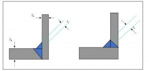
Notes:
• The cover fillet weld shall have a throat dimension not less than 𝑡𝑐
• The cover fillet weld shall provide a smooth transition from the branch to the header pipe
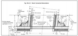
The Reinforcement Zone
The code is basically limiting the area where any reinforcement is particularly effective. B31.3 states that this area takes the shape of a parallelogram as a result of the increased stresses around the discontinuity which are considered the greatest at the edges of the opening.
The limits of reinforcement (two sides of the parallelogram) are determined as follows;
• The length along the header pipe is taken from the centreline of the branch pipe and extends in either direction as defined by 𝑑2;
- 𝑑2 = the greater of;
- 𝑑1 (opening size in the header) or
- (𝑇𝑏− 𝑐)+(𝑇ℎ− 𝑐)+ 𝑑1/2
But in no case can this exceed the outside diameter of the header pipe (𝐷ℎ)
•The limits regarding the width of reinforcement (perpendicular to the header) starts from the inside surface of the header pipe (in its corroded condition) and extends along the axis of the branch for a distance defined by 𝐿4;
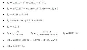
o 𝐿4 = the lesser of;
- 2.5(𝑇𝑏− 𝑐) or
- 2.5(𝑇ℎ− 𝑐)+𝑇𝑟
Calculating Branch Connections: ASME B31.3 Para. 304.3.2. Worked Example:
You are to determine if the opening created for the branch connection is adequately supported with the details provided below or whether the addition of a reinforcement ring is needed based on hoop stress?
Piping system: Produced water
Configuration: Main header NPS 10 with an abutting branch (NPS 4) welded at right angles
Piping Specification: A106 Gr B (Both header & branch)
Wall thickness: Sch 40 (Both)
Design pressure: 350 psi
Design temperature: 250°F.
Corrosion allowance: 0.12 in
Attachment welds in accordance with the details provided in para. 328.5.4.
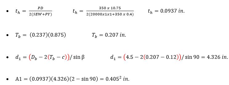
Step 1:
Calculate the required area (A1) required for a branch connection under internal pressure using;
A1= th x d1(2−sinβ)
Prior to calculating A1 determine the following variables; 𝑡ℎ,𝑑1,𝑇𝑏& sinβ
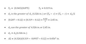
Step 2:
Determine if there is an excess thickness in the header (A2) within the reinforcement zone that can be used towards replacing the material removed;
𝐴2=(2𝑑2− 𝑑1) (𝑇ℎ− 𝑡ℎ− 𝑐)
Prior to calculating A2 determine the following variables; 𝑇ℎ,𝑑2
Step 3:
Determine if there is an excess thickness in the branch pipe (A3) within the reinforcement zone that can be used towards replacing the material removed;
𝐴3=2𝐿4(𝑇𝑏− 𝑡𝑏− 𝑐)/sinβ
Prior to calculating A3 determine the following variables; 𝐿4,𝑡𝑏
Step 4:
Determine if there is an excess thickness in the fillet cover attachment welds (A4) between the branch and header that can be used towards replacing the material removed;
Prior to calculating A4 determine the criteria for 𝑡𝑐 in para 328.5.4 shall be met;
The cover fillet weld shall have a throat dimension not less than 𝑡𝑐
• 𝑡𝑐 𝑖𝑠 𝑡ℎ𝑒 𝑙𝑒𝑠𝑠𝑒𝑟 𝑜𝑓 0.7𝑇𝑏 𝑜𝑟 0.25 𝑖𝑛.(6 𝑚𝑚)
• 𝑡𝑐 𝑖𝑠 𝑡ℎ𝑒 𝑙𝑒𝑠𝑠𝑒𝑟 𝑜𝑓 (0.7)(0.207) 𝑜𝑟 0.25 𝑖𝑛.
• 𝑡𝑐 𝑖𝑠 𝑡ℎ𝑒 𝑙𝑒𝑠𝑠𝑒𝑟 𝑜𝑓 0.145 𝑖𝑛.𝑜𝑟 0.25 𝑖𝑛.=0.145 𝑖𝑛.
• The size of the fillet weld based on the minimum leg dimension is 0.145/0.707=0.205 𝑖𝑛.
• 𝐴4=2(0.5)(0.205)2= 0.04202 𝑖𝑛.
Step 5: (Findings and conclusions)
Is the area removed (A1) sufficiently replaced by the material available within the limits of the reinforcement zone i.e. A2 + A3 + A4 ≥ A1.
A1 = 0.405 in.
A2 = 0.456² in.
A3 = 0.0209² in.
A4 = 0.0420² in.
• We should have noticed that there is excess material from A2 alone to replace the area required and no additional reinforcement (pad) is required for this worked example.
• The total material available within the defined reinforcement zone (A2+A3+A4) is calculated at 0.5189² in
We cover many of these more challenging technical issues in our ASME Plant Inspector Level 3 course. Want to become a Principal Plant Inspector, the level 3 is a great place to start.
