- Home
- About
- Training Courses
- ASME Courses
- API Courses
- API 510 Pressure Vessel
- API 570 Process Pipework
- API 653 Aboveground Storage Tank
- API 936 Refractory Personnel
- API 580 RBI Online
- API 580 RBI Classroom *New*
- API 571 Corrosion & Materials Online
- API 571 Corrosion & Materials Classroom *New*
- API 577 Welding Inspection & Metallurgy Online
- API 510 CPD Training
- API 570 CPD Training
- API 1169 Pipeline Construction
- API SIFE Source Inspector Fixed Equipment
- API SIRE Source Inspector Rotating Equipment
- E-Learning
- Technical Courses
- API CPD Recertification
- Training Courses
- Technical Hub
- Virtual Training
- FAQs
- Contact
- Online Training Portal
- Shop

- In: Training | On: Oct 13, 2020
Fracture Mechanics – Intro
Fracture Mechanics – When does it apply?
Fracture Mechanics – When does it apply? A question we are often asked. There are two approaches to design. Many pressure equipment design codes use the traditional ‘strength of materials’ approach. Ask an API 510, API 570 or ASME level 2 Plant Inspector how to calculate the required wall thickness of a pressure-retaining shell and they will duly complete a code calculation using the allowable stress of the material at coincident temperature and design pressure.
This can be termed a ‘strength of materials’ approach. Essentially, the calculated wall thickness ensures that the applied stress does not exceed the materials yield or ultimate tensile strength. It does this by building in a factor of safety (allowable stress) which will generally prevent the applied stress from exceeding two-thirds of yield or one-third ultimate tensile strength (at least for carbon and low alloys and varies with design code)
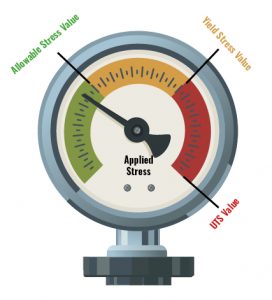
Fig 1. Strength of materials approach
In addition to the strength of the material, the codes will also place a requirement on the ductility and impact toughness of a material to guard against brittle fracture. In some cases, where the thickness and minimum design temperature exceed that of the code requirements, the material will be subjected to Charpy Impact testing as a form of qualification. But that’s for another post.
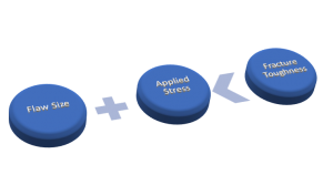
So, what about this fracture mechanics? Well, there is another approach to design. This fracture mechanics approach uses 3 important variables. Those are;
- Flaw Size
- Applied Stress
- Materials Fracture Toughness
Fracture mechanics essentially quantifies the critical combination of these variables. In its simplest form, if the flaw size and applied stress levels are kept below the fracture toughness of the material, failure should not occur.
Why is fracture mechanics relevant to the in-service integrity professionals? Well, when assessing crack-like defects, fracture mechanics can provide essential information for determining acceptable crack lengths and depths.
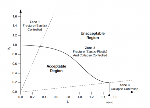
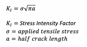
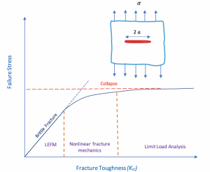
Consider a cracked plate (with an infinite plane) that is loaded uniformly to failure. Figure 2 is a schematic plot of failure stress versus fracture toughness (KIc). For low toughness materials, brittle fracture is the governing failure mechanism, and critical stress levels vary linearly with KIc. This critical stress level can be predicted by the following equation.
At very high toughness values, Linear Elastic Fracture Mechanics (LEFM) are no longer valid, and failure is governed by the flow properties of the material. At intermediate toughness levels, there is a transition between brittle fracture under linear elastic conditions and ductile overload. Non-linear fracture mechanics bridges the gap between LEFM and collapse.
If toughness is low, LEFM is applicable to the problem, but if toughness is sufficiently high, fracture mechanics ceases to be relevant to the problem because failure stress is insensitive to toughness; a simple limit load analysis is all that is required to predict failure stress in a material with very high fracture toughness.
The theory of Fracture mechanics is extensive. It is not something usually undertaken by an inspector, but only highly trained and qualified experts. However, having some understanding of the principles, we feel, should be beneficial to anyone who assesses pressure equipment degradation.
The subject is covered in our ASME Plant Inspector Level 3 course and API 579 Fitness for Service training course where we introduce the Failure Assessment Diagram (FAD)