- Home
- About
- Training Courses
- ASME Courses
- API Courses
- API 510 Pressure Vessel
- API 570 Process Pipework
- API 653 Aboveground Storage Tank
- API 936 Refractory Personnel
- API 580 RBI Online
- API 580 RBI Classroom *New*
- API 571 Corrosion & Materials Online
- API 571 Corrosion & Materials Classroom *New*
- API 577 Welding Inspection & Metallurgy Online
- API 510 CPD Training
- API 570 CPD Training
- API 1169 Pipeline Construction
- API SIFE Source Inspector Fixed Equipment
- API SIRE Source Inspector Rotating Equipment
- E-Learning
- Technical Courses
- API CPD Recertification
- Training Courses
- Technical Hub
- Virtual Training
- FAQs
- Contact
- Online Training Portal
- Shop
- In: Training | On: Mar 15, 2022
API 579/ASME FFS-1 Changes
Sometimes, A Little Change Is A Good Thing
Fitness For Service Training – API 579/ASME FFS-1 – must be up there as one of the most comprehensive and helpful resources out there in the world of technical codes and standards.
First published in January 2000 it provides the refining and petrochemical industry with various methods for the reliable assessment of equipment’s structural integrity containing identified flaws or damage. Over the years, the standard has evolved to the latest edition issued in December 2021 with some significant changes.
A complete list of these changes can be found in the foreword of the latest edition; however, in this article, we will look at the relevant changes that impact the assessment methods for wall loss. Then, perhaps in a later edition of Integrity Matters, we will look at other parts of the standard, and the impact changes may have.
It’s not the intent of this article to teach readers how to do a fitness-for-service assessment; we’ve already covered that on our website. So instead, why not look under the technical hub page to see how to conduct part 4 evaluation? But, of course, the original article is out of date due to the changes in the latest edition covered in this article.
Part four of API 579 covers the assessment of general metal loss. In the previous edition of 579, two assessment methods were available under part 4. The profile of the wall loss dictated which method to use. For example, if the wall loss was uniform (had a smooth profile), then point thickness readings (PTR) were used in the assessment. However, if the loss profile was non-uniform, i.e. there was a greater variance across the data set, then critical thickness profiles (CTP) would be used to calculate the average thickness.
Let us take a look at the changes to Part 4.
First to mention is the inclusion of the helpful table 4.2. This table compartmentalises the different component types along with their definition and some example component types to assist users in identifying which type they are assessing. The previous edition buried the component types across multiple paragraphs that were not user-friendly. A warm welcome then; however, it is still the user’s responsibility to verify that piping temperature limits and vessel diameter to span or height ratios still meet specific criteria to be classed as a type A component.
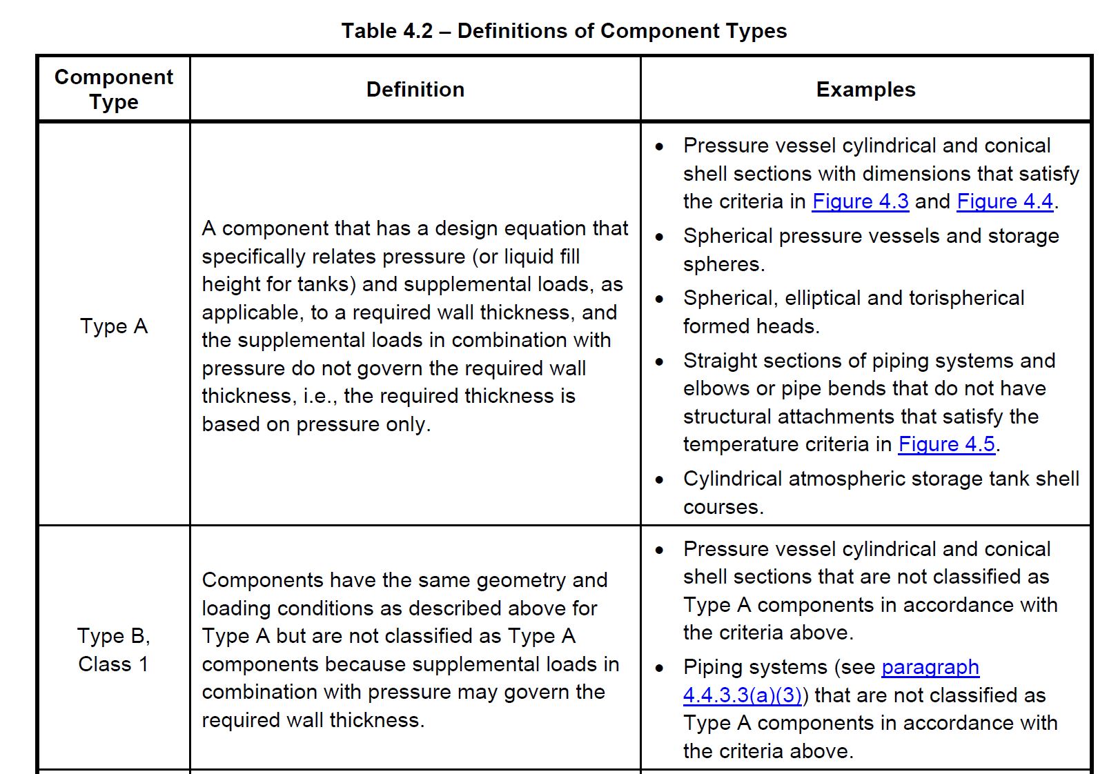
Extract from the new Table 4.2 clarifying component types. Credit API 579/ASME FFS-1 December 2021
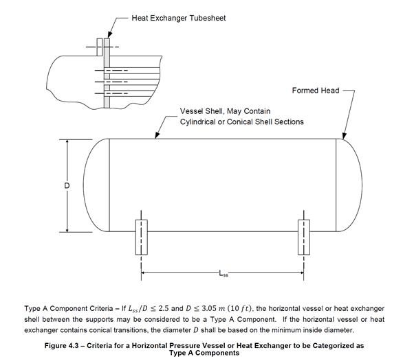
Example of a Type A component check for cylindrical shells. Credit API 579/ASME FFS-1 December 2021
Interestingly, 2:1 head to shell junctions (on the SHELL side) has been reclassified from Type C to Type A components when hoop stress governs.
Next on the list is the explanation of the minimum measured thickness criteria. Many assumptions have been made in the past regarding this value. For example, previous thoughts were to protect against structural failure or failure due to accidental damage such as impact. While these may have some element truth about them, API/ASME has provided the following statement.
“The Level 1 and Level 2 Assessment procedures include a limitation on the minimum measured thickness, tmm. The limitation on tmm is to guard against potential inadequacy in inspection method capabilities to characterise excessively thinned areas accurately. If the limitation on tmm is not satisfied, a Level 3 Assessment may be performed. Future inspection frequency shall be established based on a detailed investigation of all applicable damage mechanisms, and inspection results shall be appropriately validated”.
So, there we have it, the settlement of many an argument, the limit is to protect against inaccuracies in the measured wall thickness – makes sense.
The standard further provides recommendations for validating inspection results when the thickness recorded is ≤2.5mm. These are;
a) Confirm appropriate instrument calibration for the full range of measured thickness values.
b) Perform multiple forms of NDE or utilise multiple inspectors to validate inspection findings.
c) Validate inspection method accuracy with a mock-up sample representing the actual field conditions(considering operating temperature, measured thickness ranges, damage profile, etc.), insofar as possible.
d) Increase inspection frequency to confirm damage progression rate.
One of the most significant changes in this edition is the additional restriction when determining whether to use Point Thickness Readings (PTR) or Critical Thickness Profiles (CTP). This has been implemented to prevent ‘smoothing out local variations’ and requires the minimum measured thickness to be no less than 90% of the average measured thickness. If this requirement is not met, the user should use the CTP method. In effect, this now replaces the previous coefficient of variation (COV) assessment and prevents the user from artificially turning non-uniform loss into uniform loss during the COV calculation.
Removing the COV calculation will please many on our Fitness For Service Training – API 579/ASME FFS-1 courses!
When using the CTP method, the new edition has now included the inspection plane requirements based on component geometry in step 2 of the assessment methodology. Inspection planes need only be in relation to the governing stress for cylinders. Inspection plane spacing requirements have also been simplified to;
![]()
This is a sensible change, as the previous edition required a calculated value based on the remaining thickness ratio. This wasn’t always completed ‘at the coal face’ when marking out the assessment grid, so this simplified approach will please many. Note, however, that this is not mandatory, and spacing to suit the profile of the wall loss can be made so that it is better characterised.
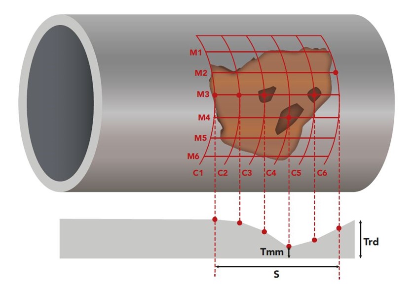
Recommend grid spacing has been simplified in the latest edition.
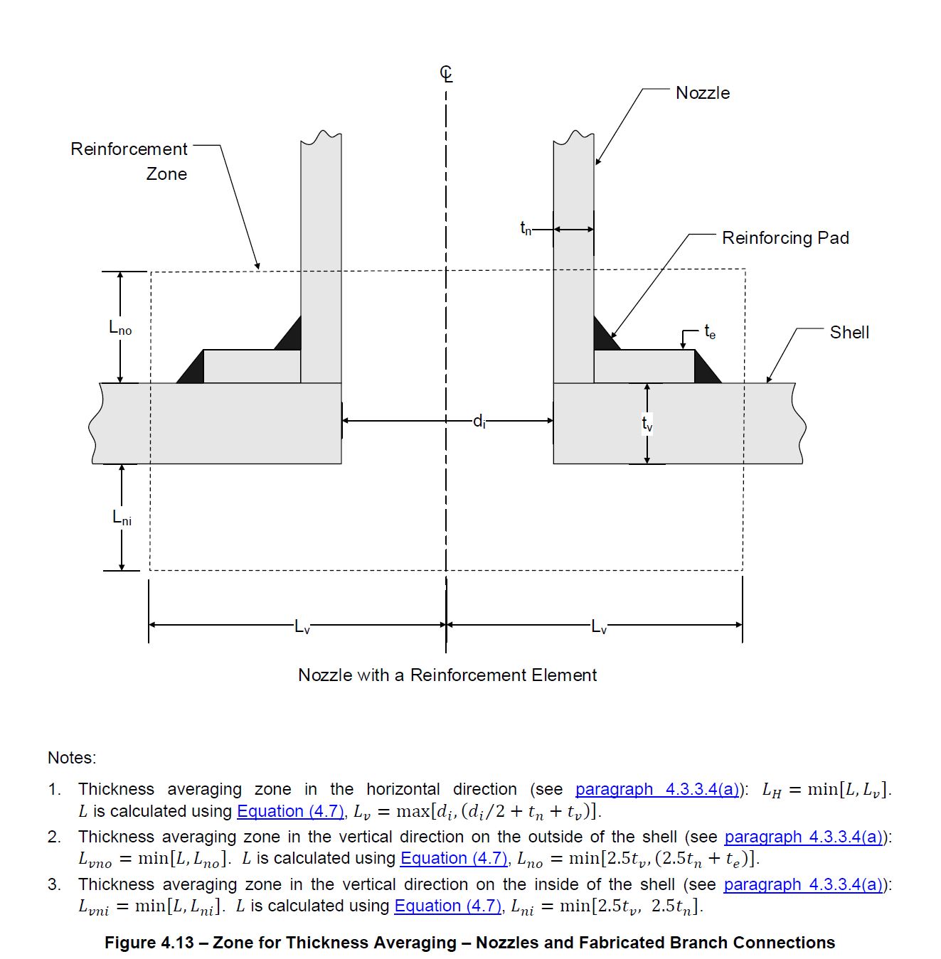
The thickness averaging zone limits have also been amended for taking thickness in regions of nozzles/structural discontinuities. This is to ensure the method does not permit greater damage at nozzle junctions vs. away from nozzle junctions.
Outside of Part 4 there are other changes to consider when assessing wall loss. Probably the most significant is removing the ability to use ASME VIII Div 2 allowable stress under certain circumstances.
This was previously detailed in Annex 2C.2.4 and allowed the allowable stress from Div 2 to be used for Div. 1 vessels when the flaw is located in the base material of a cylindrical, conical or spherical shell outside of the weld band.
So why has this been removed? Well, it was a legacy carried over from API 510 at a time when the factor of safety of Div 2 was 3.0. This has subsequently been revised to the current 2.4, resulting in a factor of safety deemed too low for a design by rule pressure vessel.
These are the significant changes in Part 4 of the 2021 edition of the API 579/ASME FFS-1 Standard. There may be others, but we’ve still to digest the 1478 PDF pages while we update our popular Fitness For Service Training – API 579/ASME FFS-1 courses.
