- Home
- About
- Training Courses
- ASME Classroom & Virtual Courses
- API Classroom Courses
- E-Learning
- ASME Level 1 eLearning - Full Course
- ASME Plant Inspector Level 1 – Block 1 (Intro and Modules 1 and 2)
- ASME Plant Inspector Level 1 – Block 2 (Modules 3-5)
- ASME Plant Inspector Level 1 – Block 3 (Modules 6-8)
- ASME Plant Inspector Level 1 – Final Examination Module
- ASME Level 2 eLearning - Full Course
- ASME Plant Inspector Level 2 – Block 1 (Modules 1-3)
- ASME Plant Inspector Level 2 – Block 2 (Modules 4-7)
- ASME Plant Inspector Level 2 – Block 3 (Modules 8-10)
- ASME Plant Inspector Level 2 – Final Examination
- API 579 Fitness For Service
- API 571 Corrosion and Materials
- API 577 Welding & Metallurgy
- API 580 Risk Based Inspection
- API 510 CPD Training
- API 570 CPD Training
- API SIFE
- API 1169 Pipeline Inspector Certification Course
- API 936 Refractory Personnel Certification
- Technical Courses
- API CPD Recertification
- Training Courses
- Technical Hub
- Virtual Training
- FAQs
- Contact
- Online Training Portal
- Shop
- Privacy Policy
- In: Training | On: Jun 30, 2021
Fitness For Service – stay in the game.
What is fitness for service?
Fitness For Service (FFS) assessments are a set of methods that use quantitative data to determine if a degraded component is fit for continued service at the current operating parameters and to establish the useful remaining life of the component. Some case examples are found in this research paper.
It is an analysis that can influence the run, re-rate or repair decisions and is applicable to pressure vessels, storage tanks, pipework, pipelines and boilers. These types of pressure equipment can be grouped into the term fixed (or static) pressure equipment.
Rotating equipment are components such as pumps, compressors and turbines. These are excluded from the FFS methods presented in this article, however, it should be noted that the pressure boundary of rotating equipment is covered within the FFS methodologies in API 579/ASME FFS-1 and other international standards.
Once an item of pressure equipment is placed into service it is likely to suffer from some form of degradation caused by the process environment. This may be due to the fluid, external atmospheric conditions or cyclic and/or thermal loadings.
The driving force behind the degradation is known as a Damage Mechanism. Note how the term corrosion mechanism is not used as it’s not always corrosion that causes damage. Identifying the Damage Mechanism is a critical factor in conducting FFS assessments as this will determine the type of assessment used and also the future degradation rate of the component. This is crucial in establishing the remaining life.
The API 579/ASME FFS-1 (The Standard) provides technically sound consensus approaches to ensure safety while the ageing plant continues to operate and can be used to optimise maintenance and operation practices. It is an excellent publication and is widely accepted throughout the world across many industries.
Scope of API 579/ASME FFS-1 2016 Edition
The assessment procedures in API 579 can be used for FFS assessments and/or re-rating of equipment designed and constructed to the following codes:
a) ASME B&PV Code, Section VIII, Division 1
b) ASME B&PV Code, Section VIII, Division 2
C) ASME B&PV Code, Section I
d) ASME B31.1 Piping Code
e) ASME B31.3 Piping Code
f) ASME B31.4 Piping Code
g) ASME B31.8 Piping Code
h) ASME B31.12 Piping Code
i) API Std 650
k) API Std 530
Other Recognised Codes and Standards
The assessment procedures may also be applied to pressure-containing equipment constructed to other recognised codes and standards, including international and internal corporate standards. The standard has broad applications since the assessment procedures are based on allowable stress methods and plastic collapse loads for non-cracklike flaws, and the Failure Assessment Diagram (FAD) approach for crack-like flaws.
As PD5500 and EN13445 are both recognised international codes, then it’s clear that the methods in API 579 are applicable to pressure vessels constructed to these codes.
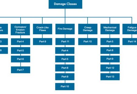
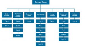
API 579 is conveniently divided into 14 parts, each with multiple annexes detailing the assessment methodologies depending on the damage mode.
An overview of the contents is listed below;
• Part 1 – Introduction
• Part 2 – FFS engineering Assessment Procedure
• Part 3 – Brittle fracture
• Part 4 – General metal loss
• Part 5 – Local metal loss
• Part 6 – Pitting corrosion
• Part 7 – Blisters and HIC/SOHIC damage
• Part 8 – Weld misalignment and shell distortion
• Part 9 – Crack-like flaws
• Part 10 – Creep
• Part 11 – Fire damage
• Part 12 – Dents and gouges
• Part 13 – Laminations
• Part 14 – Fatigue Damage
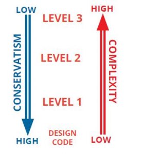
Each method has 3 levels of assessment, decreasing in conservatism as the level increases. Level 3 often requires Finite Element Assessment (FEA) and expectedly is more complex than levels 1 and 2.
The Standard acknowledges that inspectors should be capable of conducting a level 1 assessment, although it should be noted the analysis should be verified by an Engineer. It is stipulated in The Standard that the inspector shall have experience in inspection, examination, or both, of the type of equipment and associated process that is
subject to the FFS assessment.
Input into the assessment may come from a number of stakeholders and will be determined by the complexity and criticality of the assessment. The Standard defines each of the responsibilities, but a summary is provided.
Owner-operator
• Assumes overall responsibility for the Fitness For Service (FFS) assessment
Inspector
• Responsible to the Owner-Operator
• Collection and collation of inspection data required for FFS
• May also perform screening assessment (API 579 / ASME FFS 2016)
Engineer
• Performs most types of assessment
• Provides documentation
• Produces guidance for future operation (run, repair, replace)
Materials Engineer
• Damage mechanisms identification
• Material properties
• Growth parameters
NDE Engineer
• Damage detection and characterisation
Process Engineer
• Past, present and future operational requirements
• Normal and upset conditions
Assessment Procedure
Part 2 of The Standard outlines the high-level assessment procedure. The steps for all assessments follow this procedure.
Step 1 – Flaw and damage mechanism identification
Step 2 – Applicability and limitations of the FFS assessment procedures
Step 3 – Data requirements
Step 4 – Assessment techniques and acceptance criteria
Step 5 – Remaining life evaluation
Step 6 – Remediation
Step 7 – In-service monitoring
Step 8 – Documentation
These steps are applicable to the various methods of assessment and should be completed in a methodical and systematic manner to ensure that all required data is collected and the correct process is followed.
Step 1 – Flaw and damage mechanisms
The first step in the assessment process is to identify the flaw type (damage mode) and the cause of the damage (damage mechanism), this determines which assessment method to utilise.
Step 2 – Applicability and Limitations of assessment
Once the correct assessment method has been selected, the applicability and limitations of that part should be reviewed to ensure that the assessment technique is valid.
Step 3 – Data Requirements
The following items should be included in the documentation.
Original equipment design data such as;
• Manufacturer’s Data Report or other equivalent documentation or specifications.
• Fabrication drawings showing sufficient details to permit calculation of the MAWP of the component containing the flaw.
• If a re-rate to a different condition of pressure and/or temperature is desired (i.e. increase or decrease in conditions), this information should be available for all affected components.
• Detailed sketches with data necessary to perform MAWP calculations may be used if the original fabrication drawings are not available.
• The inspection records for the component at the time of fabrication.
• User Design Specification if the vessel is designed to the ASME Code, Section VIII, Division 2.
• Material test reports.
• Pressure-relieving device information including pressure relief valve and/or rupture disk setting and capacity information.
• A record of the original hydrotest including the test pressure and metal temperature at the time of the test or, if the metal temperature is unavailable, the water or ambient temperature.
• Piping line lists or other documentation showing process design conditions, and a description of the piping class including material specification, pipe wall thickness and pressure-temperature rating.
• Piping isometric drawings to the extent necessary to perform an FFS assessment. The piping isometric drawings should include sufficient details to permit a piping flexibility calculation if such an analysis is deemed necessary by the Engineer in order to determine the MAWP of all piping components. Detailed sketches with data necessary to perform MAWP calculations may be used if the original piping isometric drawings are not available.
• Type of flaw and characterisation of the flaw including all sizing data. Inspection data including all readings utilised in the FFS assessment.
This list is by no means exhaustive, the data required will depend on the flaw type being assessed.
STEP 4 – Assessment Techniques and Acceptance Criteria
Three levels of assessment are provided. In general, each assessment level provides a balance between conservatism, the amount of information required for the evaluation, the skill of the personnel performing the assessment and the complexity of analysis being performed.
Level 1 is the most conservative but is easiest to use. It is usual to proceed sequentially from a Level 1 to a Level 3 analysis (unless otherwise directed by the assessment techniques).
Level 1 Assessment
The assessment procedures included in this level are intended to provide conservative screening criteria that can be utilised with a minimum amount of inspection or component information. A Level 1 assessment may be performed either by plant inspection or engineering personnel.
Level 2 Assessment
A level 2 assessment is intended to provide a more detailed evaluation that produces results that are more precise than those from a Level 1 assessment. In a Level 2 Assessment, inspection information similar to that required for a
Level 1 assessment is needed; however, more detailed calculations are used in the evaluation. Level 2 assessments would typically be conducted by plant engineers, or engineering specialists experienced and knowledgeable in performing FFS assessments.
Level 3 Assessment
Level 3 provides the most detailed evaluation that produces results that are more precise than those from a Level 2 assessment. In a Level 3 Assessment, the most detailed inspection and component information is typically required, and the recommended analysis is based on numerical techniques such as the finite element method
or experimental techniques when appropriate. A Level 3 assessment is primarily intended for use by engineering specialists experienced and knowledgeable in performing FFS assessments.
FFS Acceptance Criteria
FFS assessment methodologies utilise one or more of the following acceptance criteria;
• Allowable stress
• Remaining Strength Factor (RSF)
• Failure Assessment Diagram (FAD)
Allowable stress
The allowable stress value is typically established as a fraction of yield, tensile or rupture stress at design temperature and can be associated with a design margin. The allowable stress values are used in design codes for the calculation of the minimum required wall thickness and MAWP. The ratio varies from code to code so it is necessary to establish
how the allowable stress has been determined based on the design code.
Remaining Strength Factor
Structural evaluation procedures using linear elastic stress analysis with stress classification and allowable stress acceptance criteria provide only an approximation of the loads that a component can withstand without failure.
The remaining strength factor is utilised to define the acceptability of a component for future service, which is
expressed as;
RSF = LDC / LUC
With this definition, the acceptance criteria can be established using traditional code formulas, elastic stress analysis, limit load theory, or elastic-plastic analysis.
Where,
• LDC = Limit or plastic collapse load of the damaged component (component with flaws)
• LUC = Limit or plastic collapse load of the undamaged component
The reduced MAWP for the component with the static head subtracted as appropriate, shall be compared to either the equipment design pressure (DP) or equipment MAWP.
The equipment is acceptable for continued service if the reduced MAWP is ≥ than the equipment DP or MAWP.
The equipment would be determined as unacceptable if the reduced MAWP is less than the equipment DP or MAWP.
• RSFcalculated ≥ RSFallowable (suitable for continued service)
• RSFcalculated ≤ RSFallowable (repaired, re-rated or retired)
In the next article, we will look at the definitions of stress and how they fit with FFS assessments.
Want to know more? How API 579 course goes into far more detail with many real-life worked examples to ensure you can apply the theory in the workplace. Find more on our course page. It can also be completed through our very popular elearning.
